
https://upload.wikimedia.org/wikipedia/commons/thumb/5/50/JFET_n-channel_en.svg/512px-JFET_n-channel_en.svg.png
The aim of this report is to give an introduction of the behavior of a n-chanel-JFET.
Before we start please have a quick look at the introduction of JFETs.
The voltage for the measurements and the measurement itself was carried out with a KEITHLEY 2612A SYSTEM SourceMeter.
To work with the source-meter please have a quick look at
the manual of the KEITHLEY device.
In the example-plot above we can see that there are two regimes. The first regime is called "linear region" in which the JFET behaves like a ohmic resistor. In the second regime we can see that the drain-source-current remains almost constant, this is called saturation regime.
The left plot shows how the gate-source-voltage effects the drain-source-current. We can see, that for high gate-source-voltages the drain-source current decreases to a leakage current that is almost zero.
The drain current of the linear regime can be described as
\begin{equation} I_D=I_p\left[\frac{V_D}{V_p}-\frac{2}{3}\left(\frac{V_{bi}+V_D-V_G}{V_p}\right)^{3/2}+\frac{2}{3}\left(\frac{V_{bi}-V_G}{V_p}\right)^{3/2}\right], \end{equation}and in the saturation regime as
\begin{equation} I_D=I_p\left[\frac{1}{3}-\frac{V_{bi}-V_G}{V_p}+\frac{2}{3}\left(\frac{V_{bi}-V_G}{V_p}\right)^{3/2}\right]. \end{equation}First of all we are going to measure the I-U characteristics of a n-channel-JFET. For an open gate the JFET behaves like a ohmic resistor, the JFET is therefor conductive. Now we connect the gate, source and drain and measure the drain-source-current. For this measurement we are varying the drain-source-voltage at a certain gate voltage and plot the drain-source-current over the drain-source-voltage.
Now we need to communicate with the KEITHLEY SourceMeter. For this purpose we can use the following Python script
Now we can look at the following diagram for a gate-source-voltage of 0 V. Now we can see that for increasing drain-source-voltages the drain-source-current increases to a certain point called pinch-off-voltage. If we now increase the voltage furthermore, the drain current remains almost constant.
If we do the measurement again with a applied negative gate-source-voltage, we can investigate that the space-charge-area is increasing and therefor the drain-source-current decreases. This behavior can be seen in the following diagram,

> Now we are testing how the n-channel-JFET is behaving if we increase the gate voltage to a very high level.
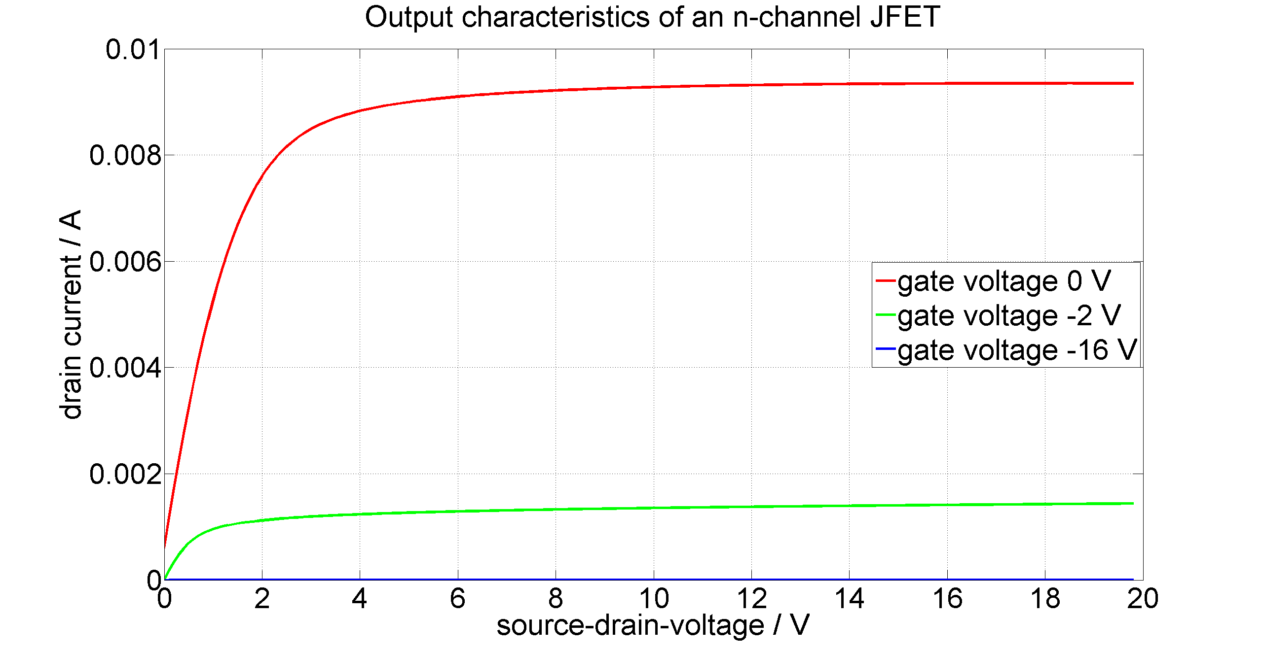
Now we can see a graph for 0 V, -2 V and -16 V. For 0 V we get the same result as in our last graph, for 2 V the drain-source-current is decreasing rapidly and for -16 V the current is almost zero, except for a small leaking current, for all applied drain-source-voltages.
Now we can calculate the drain current for no gate-source-voltage to evaluate if the current of the saturation regime matches with the calculated one. First of all we are going to assume that the bias-voltage Vbi = 0.7 V, the pinch-off-voltage Vp ≈ 7.5 V, and the pinchoff-current is estimated according to data sheets of similar n-channel-JFETs with Ip ≈ 0.06 A. If we now insert our values to the second equation we get for the drain-source-current ID ≈ 0.009 A which matches our results for a gate-source-voltage of 0 V .