A bipolar transitor is a device primarily to control larger currents with a small current using electrons as well as holes as charge carriers.
It consists of three differently doped regions (base, collector, emitter) resulting in two p-n-junctions. In case of the here discussed PNP transistor
BC327-40 the collector and the emitter are p-type and the base is n-type.
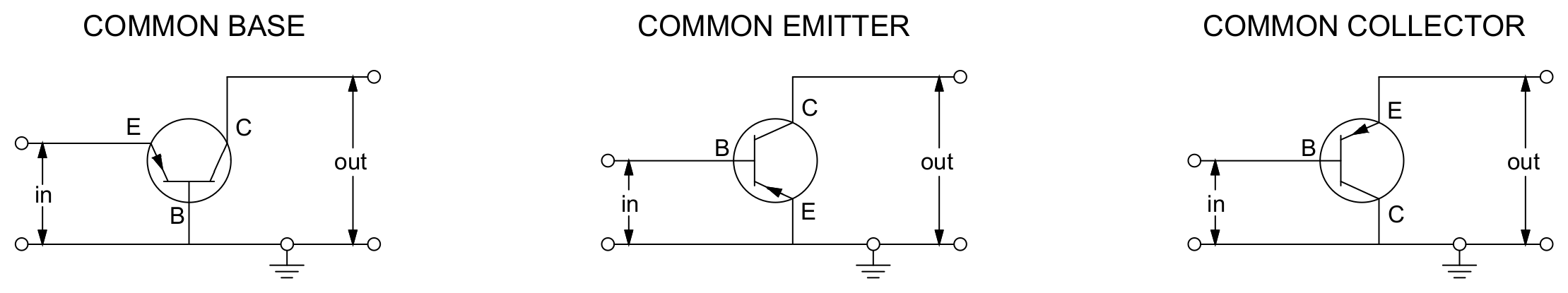
Besides using these junctions as diodes, there are three basic configurations shown in Fig. 1.
Fig. 1: Common transistor configurations: E...Emitter, B...Base, C...Collector
For all these configurations, measurements of the output current over voltage and with different input currents were conducted.
Source as well as measuring device was the
Keithley 2636A System SourceMeter, where channel A was used as the voltage source and channel B was used for current measurements.
Common Base
In common base configuration, the base is connected to ground.
It is mostly used as a high frequency voltage amplifier due to the stability that comes with the high isolation of collector and emitter.
For 7 different emitter currents ($-0.02, 0, 2, 4, 6, 8, 10$ mA) a sweep of the collector-emitter voltage $U_{BC}$ ($-8$ to $5$ V) was done and the collector current $I_C$ was recorded.
The Python script pnp_common_base.py was used to record measurements.
Fig. 2: Output characteristics of the common base configuration:
collector current $I_C$ in mA over the base-collector voltage $U_{BC}$ in V
for several emitter currents $I_E$
Download: IV_curve_solar_panel.py
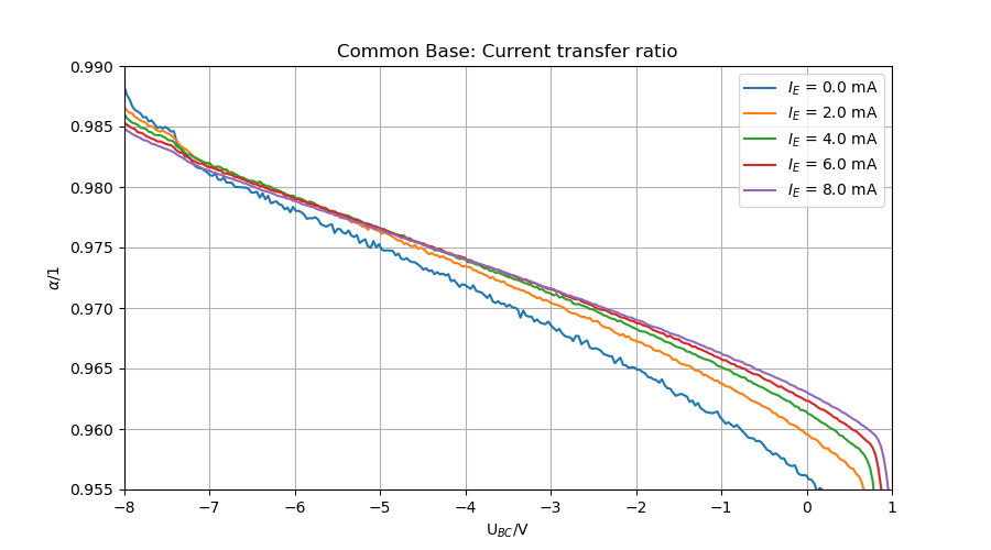
In addition, the current transfer ratio was calculated and is shown in Fig. 2
The measured values fit the typical common base output charakteristics with a
stable current transfer for voltages smaller than 0 and a breakdown at approximately 2 V
when exceeding the listed Base-Emitter On Voltage of -1.2 V.
Fig. 3: Current transfer rate $\alpha$ = $I_C/I_E$ for emitter currents $I_E > 0$ mA
and base collector voltages $U_{BC} < 1$ V
Common Emitter
The common emitter configuration is also a possibility for voltage amplification with high current gain.
As the name suggests, the emitter is connected to ground and the base is connected to the input.
For 6 different base currents ($0, 2, 4, 6, 8, 10$ $\mu$A) a sweep of the collector-emitter voltage $U_{CE}$ ($-20$ to $0$ V) was done and the collector current $I_C$ was recorded.
The Python script pnp_common_emitter.py was used to record measurements:
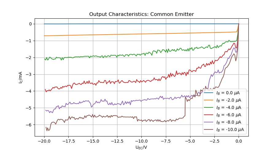
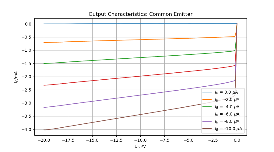
Fig. 4: Output characteristics of the common emitter configuration:
collector current $I_C$ in mA over the emitter-collector voltage $U_{EC}$ in V for several base currents $I_B$
Download: IV_curve_solar_panel.py
The observed characteristics do not resemble the expected behaviour. Based on the guess that the
sourcemeter could have troubles providing a constant current for very small resistances, a series resistor was introduced.
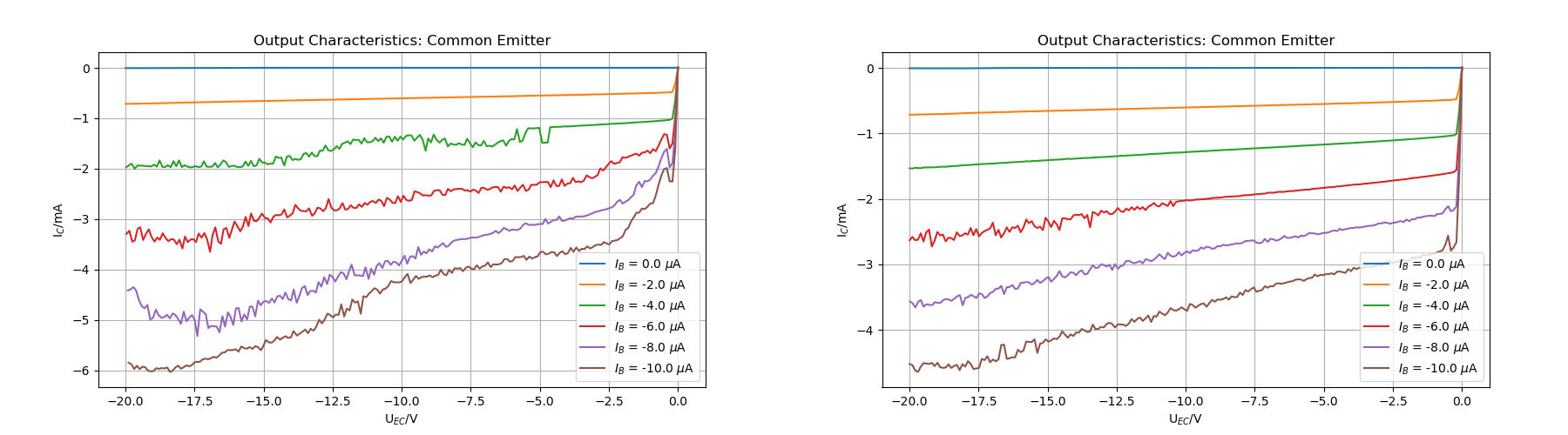
After using an 1 kOhm and a 3,3 kOhm resistor it occurs that the source still is unstable for higher currents (see Fig. 5).
Fig. 5: Output characteristics of the common emitter configuration:
collector current $I_C$ in mA over the emitter-collector voltage $U_{EC}$ in V for several
base currents $I_B$ with a series resistor of 1 k$\Omega$ (left) and 3,3 k$\Omega$ (right)
A smooth result for the chosen base currents was achieved by using a 47 k$\Omega$ resistor (see Fig. 6).
A negative effect of such a resistor is the significant decrease of the output current.
Fig. 6: Output characteristics of the common emitter configuration:
collector current $I_C$ in mA over the emitter-collector voltage $U_{EC}$ in V for several base currents $I_B$
with a series resistor of 47 k$\Omega$
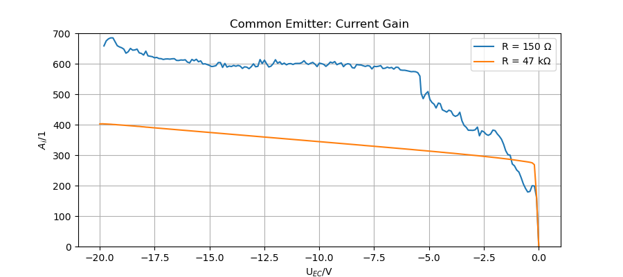
This effect appears more clearly when taking a look at the current gain $A_i$ = $I_out$/$I_in$ (see Fig. 7).
However the listed gain boudaries of A_{i,min} = 250 and A_{i,max} = 630 where neither exceeded when using no
resistor nor undercut when using the 47 k$\Omega$ resistor.
Fig. 7: current gain $A_i$ over the emitter-collector voltage $U_{EC}$ in V of the common emitter configuration with different series resistors R
Common Collector
For the last of the three configurations the emitter is connected to ground. With the
seperation of impedance levels of input and output circle and a mathematical voltage gain of 1 it typically serves as a voltage buffer.
Again the sweep of the collector-emitter voltage $U_{CE}$ ($-10$ to $0$ V) was conducted for 6 different base currents ($0, 2, 4, 6, 8, 10$ $\mu$A).
Due to the breakdown at (9.2 ± 0.1) V the current was limited to 100 $\mu$A.
Looking at the measurements (Fig. 8), a similar behaviour at higher currents as the common emitter could be observed.
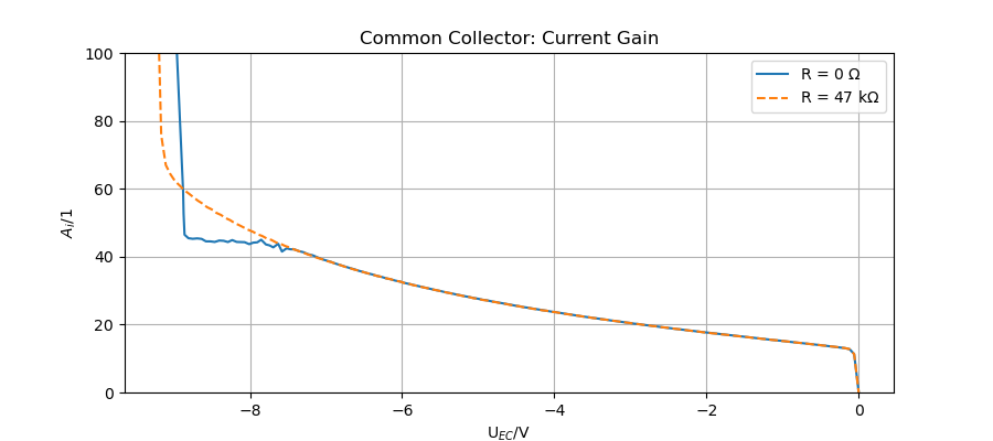
Fig. 8: Output characteristics of the common collector configuration:
emitter current $I_E$ in mA over the emitter-collector voltage $U_{EC}$ in V for several base currents $I_B$ and different series resistors R
Besides stabilizing the curve, the introduction of a resistor slightly shifts the breakdown voltage.
Significant changes in the gain are not present (see Fig. 9).
Fig. 7: current gain $A_i$ over the emitter-collector voltage $U_{EC}$ in V of the common emitter configuration with different series resistors R