1. Measurement Setup
Four-point measurement is a method to determine the electrical resistance of a thin film. As can be seen in the measuring arrangement in figure 1, a fixed current is applied via the outer contacts. The electrical voltage is then measured across the middle contacts. It is important to ensure that the contacts are positioned as centrally as possible so that the electrical current lines can spread freely and falsification of the measurement can be avoided.
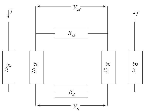
Fig.1 Measurement Setup
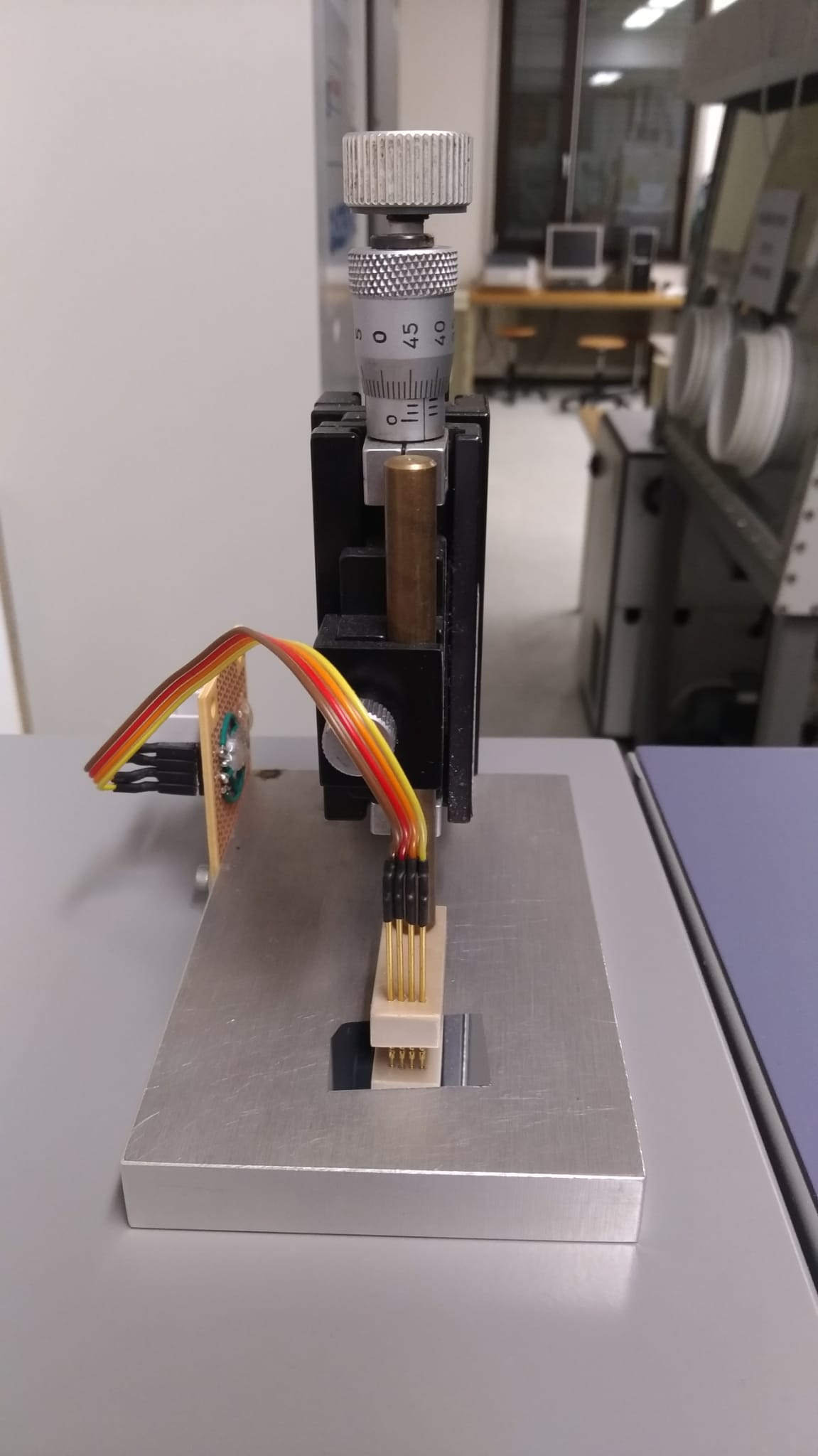
Fig.2 Measurement Device
2. Aims of the measurements
The aim of the four-point measurement was to determine the resistance of an aluminium sample as a function of temperature. For this purpose, the measuring device was placed in a humidity chamber and the resistance was measured between 15°C and 39°C. For each temperature the resistance was measured 100 times. Humidity was not considered for this measurement arrangement. Thus, a humidity of 50% with an acceptance of +- 30% was selected in the humidity chamber. Furthermore, the layer thickness of the aluminium film had to be calculated.
The following script was used to sweep the temperature SH222_sweep.py:
3. Results
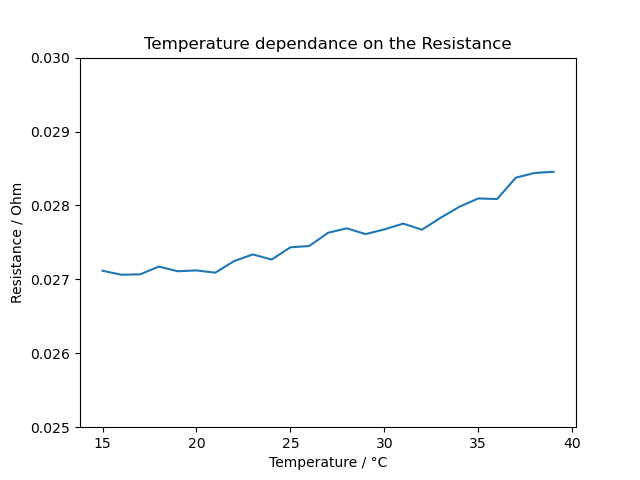
Fig.3 Temperature Curve
Script used for the Calculation of the mean of all measurements mean_of_measurements.py
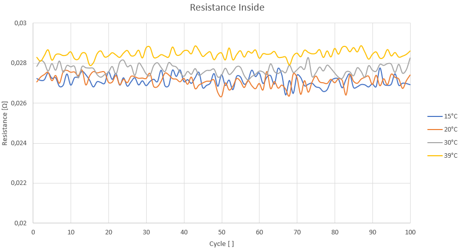
Fig.4 Inside Resistance
If the mean value of the resistances at the respective temperatures is now calculated, a certain temperature dependence of the resistance can be seen in Figure 3. In figure 4, all resistance values were plotted with the number of measurements. Due to the increasing resistance with increasing temperature, it can be shown that the observed sample is a PTC thermistor.
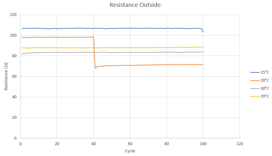
Fig.5 Outside Resistance
Figure 5 shows the resistance that could be measured through the outer pins. It is noticeable that the resistances no longer follow the above trend of figures 3 and 4. One possibility is, that the formed oxide layer broke at 20°C. As a result of this oxide layer destruction, considerably lower resistances could be achieved. Subsequently, the trend can be continued again with higher resistances at higher temperatures, even if the resistances are still lower than at 15°C.
4. Estimation of the film-thickness
There are several formulas for calculating the layer thickness, which depend on different factors. The uniformity of the contacts, the geometry of the sample or the ratio of the contact distances to the sample surface play a decisive role. Since in our case the distance between the contacts was much greater than the assumed film thickness, we could initially assume a thin film. Since our sample had a square geometry, the following simplified formula could be applied:

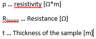
Now, with the help of the material properties at the top right and the measured resistance values, the layer thickness could be calculated. Rsquare was the averaged resistance value of all measured values at 25°C. The calculation works in principle at all temperatures, but attention must be paid to the temperature dependence of the material properties. The determined layer thickness was 0.977 μm.
For further confirmation of the calculated layer thickness, a measurement with a profilometer or the application of the scanning electrone microscope at the edge of the sample is possible.