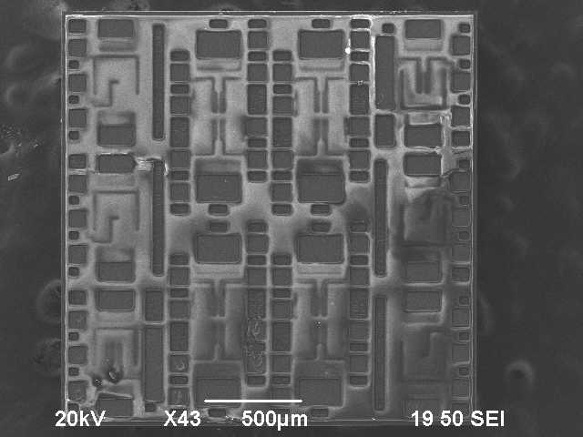
In this section of the experiment, we will test an unpackaged p-MOSFET die. Fig. 6 shows a general view of this die under an SEM.
During this test, we will use a probe to sequentially sweep voltage between Body to Source, Drain to Body, and Drain to Gate and measure the current.
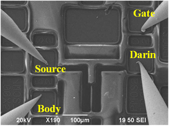
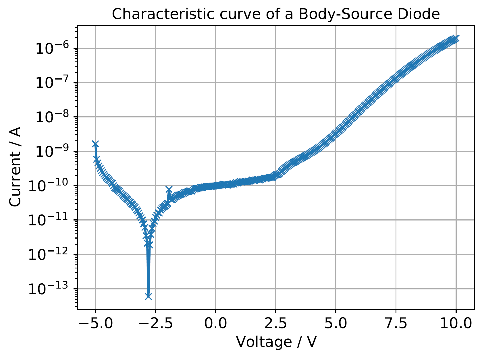
In this section, we are sweeping the voltage between Source to Body to read out the current to analyze the I-V response. The probing location is shown Fig. 8.

Fig. 9 depicts the I-V curve we measured. The lowest current reading is not located exactly at 0 V in this case. It could be because the ambient light in probing chamber is not absolutely dark, or the thermal effect shifts the 0V current location. The current shows a symmetric response between -4V and 10 V. But at -5 V, the current starts increasing significantly steeper. This may be caused by the bias voltage exceeding the reverse bias break down voltage. In this case the diode between body and source could act as short-circuit with a small resistance. Another possible explanation us that, due to the reverse bias increasing, the size of depletion zone is changing.
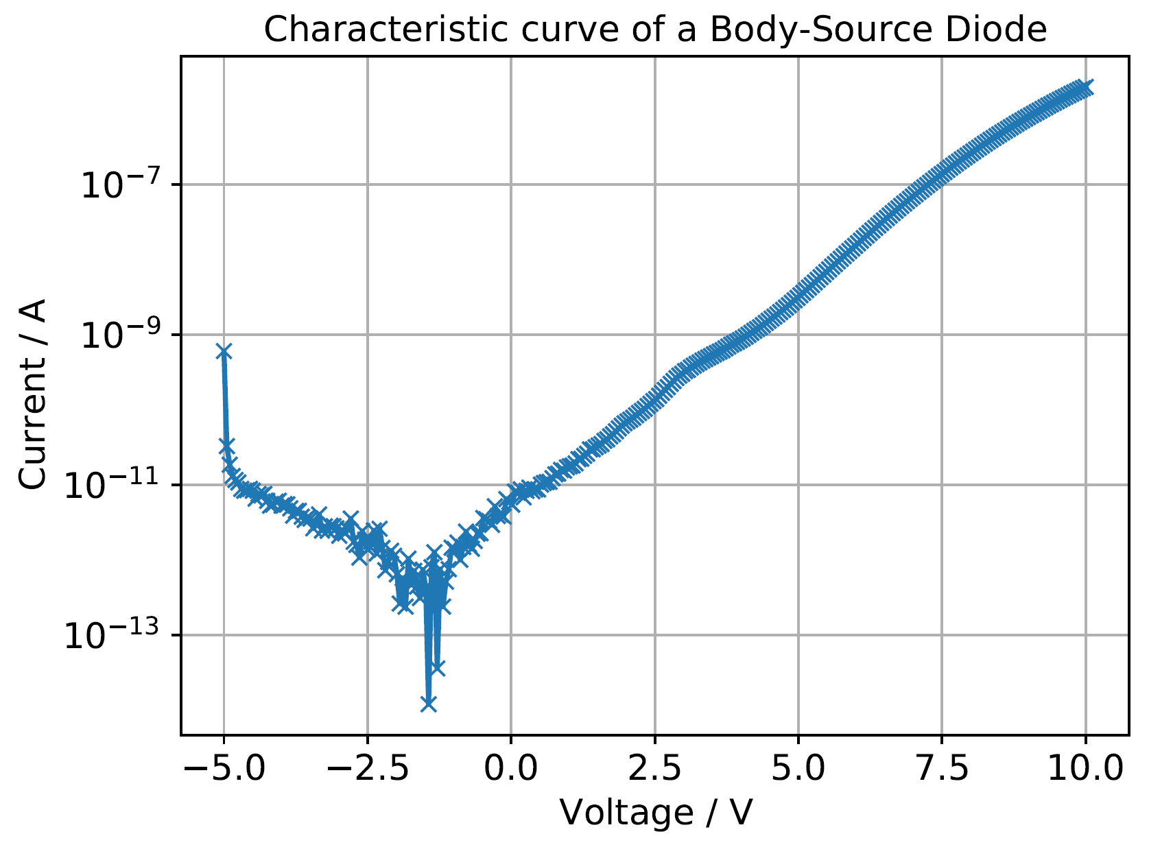
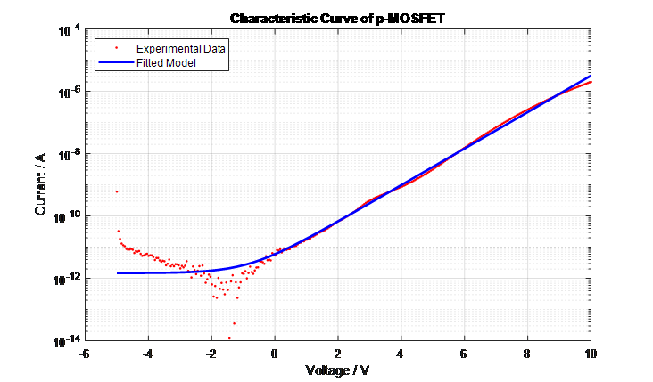
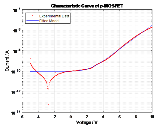
Fig. 10 shows the comparison between measured I-V curve and the fitted model we created in the previous section. Due to the complexity of the reverse bias behavior, we are unable to modeling it properly to match the measured data with the standard Schockley equation.
Here is link to matlab fitting code.
You can download the raw data here.
Fig. 11 shows the probing location for this part of experiment. It share the same sweeping strategy with previous sections.

Fig. 12 shows similar behavior as Source-Body. In an ideal situation, we expect the lowest current shown at 0 V bias voltage. In this case, the lowest voltage is shown around -2.8 V. This shift may not be caused by the ambient light or temperature due to the test environment already being well controlled. We are unable to explain this large voltage shift, also it does not match the Schockley I-V equation behavior at 0 V bias.
In Fig. 13, we use the same modeling technique from the previous sections to fit the model for this section.
Here is link to matlab fitting code.
You can download the raw data here.
In this section, we have connected each of the four pins of the MOSFET using four probes. Externally we shorted Body to Drain.
In the control program, we first set the source meter to sweep the voltage from -10V to 0V in steps of 1V between Drain to Gate. Also, every time the voltage from Drain to Gate is stepped once, the source meter scans the voltage from 0 to -10V, also in steps of 1V between Drain to Source. Then we are trying to read the current between Gate to Drain and Drain to Source.

The current read is not matched with our expectation after multiple attempts. Since we do not know the turn on voltage between Gate to Drain. So we further extend the Gate to Source voltage from -20 V to 0Vbut it still does not give any reasonable read out. In the end, we extend the voltage range from -80 to 0 V, and there is no evidence to approve the Gate is turned on, the current reading between Drain to Source is still close to the dark current read out.