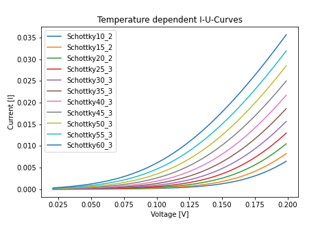
In the following experiments, physical properties of a Schottky diode have been measured. For this purpose, the Diode was heated under different conditions in an climate chamber and the ambient temperature (corresponding to the device temperature in a good approximation) and current-voltage characteristics were recorded using a Python program and belonging interfaces to the devices.
The Schottky diode, also known as a hot-carrier diode, is a semiconductor diode optimized for fast switching or low forward voltage drop. Unlike conventional light emitting diodes or similar, it does not have a pn-junction, but a barrier metal-semiconductor junction. The Potential barrier induced between the metal and the semiconductor part is referred to as the Schottky barrier. A depletion zone forms in the interface in the semiconductor.
The Schottky Diode Equation is used to calculate the current-voltage curve, showing a exponential relation. For constant current forward bias or reverse bias, the equation can be written as follows:
$$ I = I_S\left(\exp(\frac{q}{n k_B T}) - 1\right)\hspace{0.5cm}\text{[A]} $$ Where $I$ is the total current, $n$ is the ideality factor, $I_S$ is the reverse-bias saturation current, $q$ is the elementary charge of the charge carrier (electron), $T$ is the temperature and $k_B$ is the Boltzmann constant.Since we are interested in the thermal behaviour of the diode, we can write the equation as displayed in the following, with $V_D$ being the forward voltage and $V_T$ being the thermal voltage.
$$ I = I_S\left(\exp(\frac{V_D}{n V_T}) - 1\right)\hspace{0.5cm}\text{[A]} $$
The current in a typical Schottky diode is transported via thermionic emission. Thermionic emission describes the temperature dependent release of electrons from an electrode. Currents coming from other sources, like diffusion, can be neglected. The non-ideality factor -1 results from the fact that in a metal semiconductor contact, no recombination happens in the depletion region.
The above shown equation for the forward current can, for the forward current being greater than the denominator of the exponential expression, be written as: $$ I_D = I_S(\exp(m V_D)) \hspace{0.5cm}\text{[A]} $$ $$ \log(I_D) = \log(I_S)\exp(\frac{V_D}{n V_T}) $$ $$ \log(I_D) = kV_D + d $$ $$ V_T = \frac{k_BT}{q} \hspace{0.5cm}\text{[V]}$$ $$ k = \frac{1}{n V_T} $$ $$ n = \frac{1}{k V_T}$$
With $d$ being the intersection of the fitted line with the y-axis and $m$ being some constant.
The Schottky diode is put into a climate chamber, with purpose to heat the device from 10°C to 60 °C. With a step size of five degrees, the current and voltage has been measured in order to get the characteristic curves.

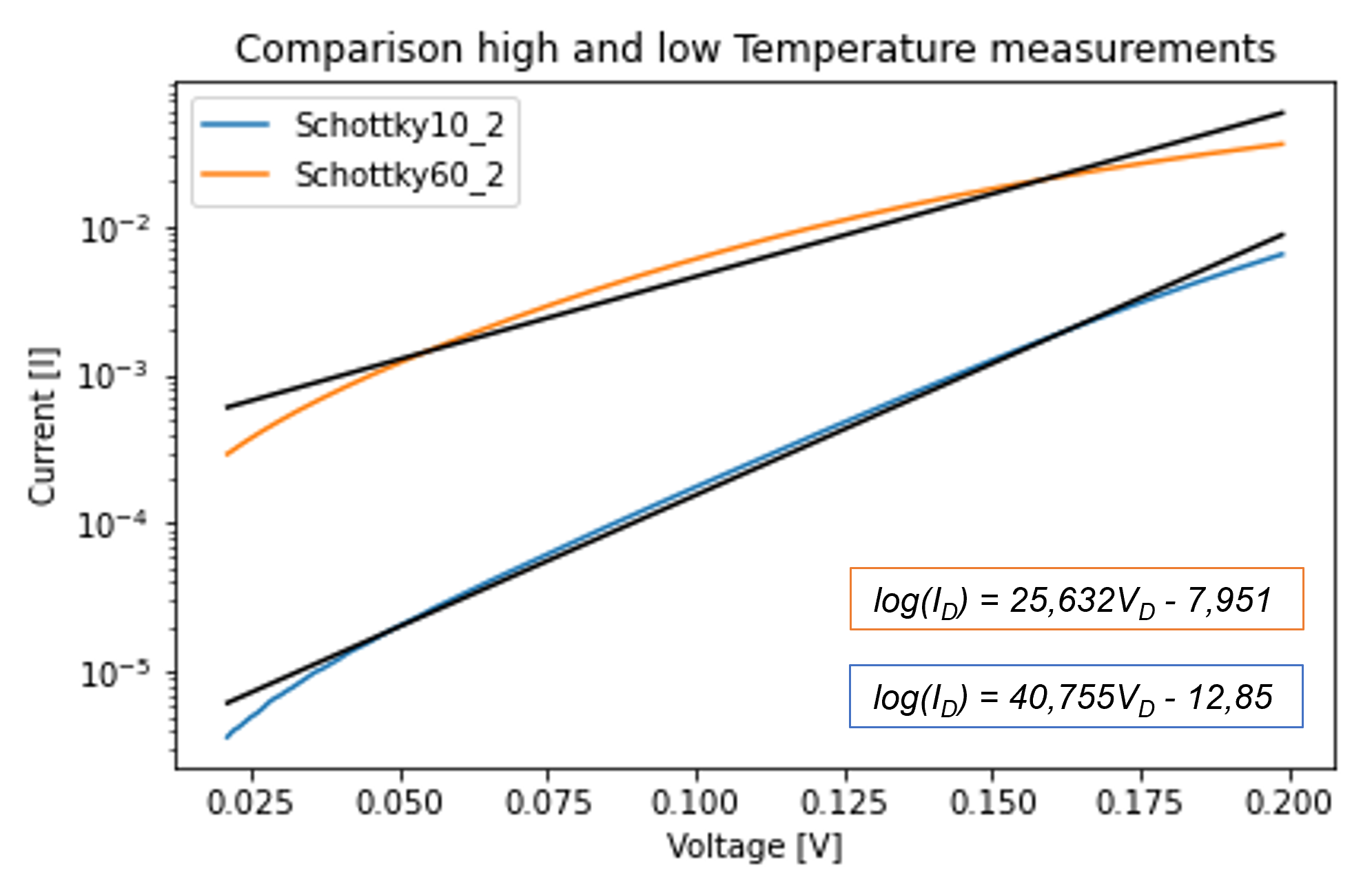
To obtain the best fitting values in the following slope-calculation of the linear parts in the logarithmic display of the data, a B-spline-Interpolation was performed for each curve, which are displayed in the Graph with their fitted lines as the black lines. With that, the linear parts of the curves were detected. This was done by hand with a python program, which fits a exponential regression onto the logarithmic data.

To better illustrate the differences at high and low temperatures, the values for 10°C and 60°C are plotted below and the corresponding linear function is shown, which has already been quoted above.

This script describes how to perform a Spline interpolation on the measured data, where $x$ refers to the measured voltage values, and $y$ to the current data. It also contains the calculations of the ideality factor, being displayed in the tables below.
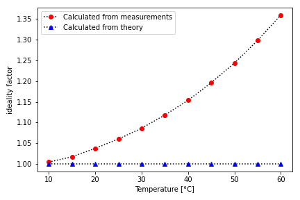
As can be seen, the best regression can be obtained for low temperatures, which results in deviations of the ideality factor being shown below.
With the above described equations and the values of the displayed slopes and linear fits, the value of the ideality factor was calculated, once for the ideal values of the slope, once for the measured and fitted values.
For comparison, the slopes calculated from the Spline interpolation and the ideal slopes for the corresponding temperature are shown in the table below, together with the thermal voltage and the ideality factor.

The behavior of an ideal diode is most reproducible for low temperatures. The ideality factor at 10°C is almost identical for both calculations, while it starts to vary as the temperature increases.
In addition, it should be mentioned that the temperature measured in the chamber is not directly related to the temperature of the diode. This also leads to deviations in the measurement results. For more information see also:
B. P. Modi and J. M. Dhimmar, "The temperature dependent ideality factor effect on I–V characteristics of Schottky diode," 2012 1st International Conference on Emerging Technology Trends in Electronics, Communication & Networking, Surat, India, 2012, pp. 1-6, doi: 10.1109/ET2ECN.2012.6470063.
R. F. Schmitsdorf, T.U. Kampen and W. Mönch, “Explanation of the linear correlation between barrier heights and ideality factors of real metal-semiconductor contacts by laterally nonuniform Schottky barriers”, Journal of Vacuum Science & Technology B 15, 1221 (1997); doi: 10.1116/1.589442
F. Triendl et al, “Theoretical and experimental investigations of barrier height inhomogeneities in poly-Si/4H-SiC heterojunction diodes”, 2020 Semicond. Sci. Technol. 35 115011
References