Semiconductor Laboratory
|
|
Semiconductor Laboratory | |
|
|
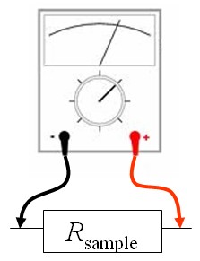
Four-wire resistance measurementsIn a simple resistance measurement, the measurement wires and the contact resistances are in series with the sample.
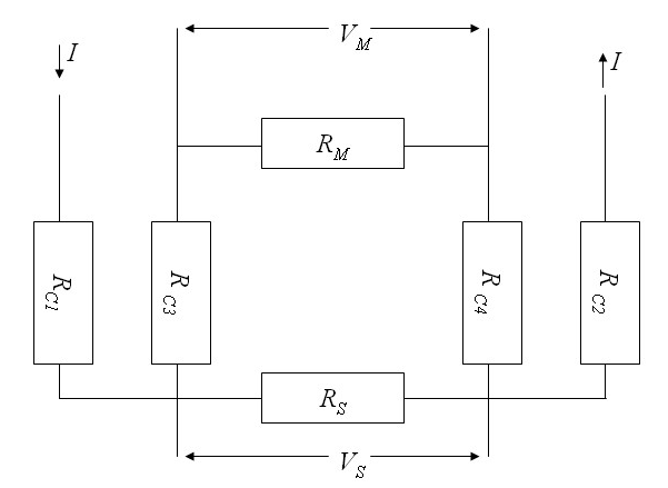
The measurement wires typically have a resistance on the order of an Ohm but the contact resistance can be in the range of MΩ or GΩ. In these cases often a 4-wire measurement is used. The equivalent circuit of this measurement is shown below.
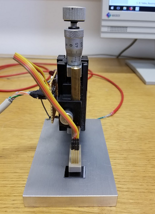
A current is driven through the outer contacts. The voltage across the terminals of the current source, \(I(R_{C1}+R_S+R_{C2})\), includes the contributions from the two contact resistances \(R_{C1}\) and \(R_{C1}\) as well as the sample resistance \(R_S\). The voltage across the sample is \(V_S=IR_S\). This voltage causes a small measurement current to flow through the voltmeter, \(I_{\text{meas}}=IR_S/(R_{C3}+R_M+R{C4})\). Here \(R_M\) is the internal reistance of the voltmeter. The voltage that the voltmeter displays is \(V_M=\frac{V_SR_M}{R_{C3}+R_M+R_{C4}}\). A good voltmeter will have a large internal resistance so \(V_M\) will be approximately \(V_S\). There will be measurement problems if the contact resistances are on the order of \(R_M\). There are four terminals of a SMU which are labeled Hi, Sense-Hi, Lo, and Sense-Lo. In a 2-wire measurement at constant current, a current is sourced from Hi to Lo and the voltage is measured between Hi and Lo. In a 2-wire measurement at constant voltage, a voltage is sourced between Hi and Lo and the current flowing between Hi and Lo is measured. In a 4-wire measurement, a current is sourced between Hi and Lo and the voltage is measured between Sense-Hi and Sense-Lo. Four-wire measurements are used in our laboratory to measure the resitivity of thin films. Four spring-loaded pogo pins are pressed against a thin flim with a micrometer screw. The Hi and Lo terminals are connected to the outer two pogo pins while Sense-Hi and Sense-Lo are connected to the inner two pogo pins.
The Python code below uses a Keithley sourcemeter to make 2-wire resistance measurements and 4-wire resistance measurements and then compares the results. Each of these measurements is repeated 10 times and the mean and standard deviation is calculated. Four point measurements on a thin filmWhen a current contact is placed on a thin conducting film with a uniform resistivity ρ and a current I is injected into this contact, the current spreads radially and the current density around the contact is,
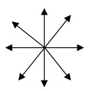
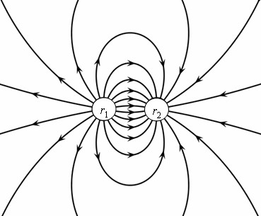
Here t is the thickness of the film. If two current contacts are placed on a thin film and a current I12 is injected into the surface at position r1 while it is extracted from position r2, then the currents just add and the folloing dipole pattern is produced. The thin film approximation is valid if the distance between the contacts is much larger than the thickness of the film.
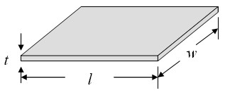
In this case the current density is given by, $$\vec{j}=\frac{I_{12}}{2\pi t}\left(\frac{\vec{r}-\vec{r}_1}{|\vec{r}-\vec{r}_1|^2}-\frac{\vec{r}-\vec{r}_2}{|\vec{r}-\vec{r}_2|^2}\right).$$The electric field is the resistivity ρ times the current density, $$\vec{E}=\rho\vec{j}=\frac{\rho I_{12}}{2\pi t}\left(\frac{\vec{r}-\vec{r}_1}{|\vec{r}-\vec{r}_1|^2}-\frac{\vec{r}-\vec{r}_2}{|\vec{r}-\vec{r}_2|^2}\right).$$The voltage between position r3 and position r4 on the surface is minus the integral of the electric field from one position to the other. The potential at r4 measured with respect to the potential at r3 is, $$V_{43}=-\frac{\rho I_{12}}{2\pi t}\int\limits_{\vec{r}_3}^{\vec{r}_4}\left(\frac{\vec{r}-\vec{r}_1}{|\vec{r}-\vec{r}_1|^2}-\frac{\vec{r}-\vec{r}_2}{|\vec{r}-\vec{r}_2|^2}\right)\cdot d\vec{r}.$$The voltage is independent of the path that is taken. We choose to integrate first in the x-direction and then in the y-direction. $$V_{43}=-\frac{\rho I_{12}}{2\pi t}\int\limits_{x_3}^{x_4}\left(\frac{x-x_1}{(x-x_1)^2+(y_3-y_1)^2}-\frac{x-x_2}{(x-x_2)^2+(y_3-y_2)^2}\right)dx \\ -\frac{\rho I_{12}}{2\pi t}\int\limits_{y_3}^{y_4}\left(\frac{y-y_1}{(x_4-x_1)^2+(y-y_1)^2}-\frac{y-x_2}{(x_4-x_2)^2+(y-y_2)^2}\right)dy.$$After performing the integration, the following expression for the voltage is found, $$V_{43}=\frac{\rho I_{12}}{4\pi t}(l_{31}-l_{32}-l_{41}+l_{42}),$$where $$l_{mn}=\ln\left((x_m-x_n)^2+(y_m-y_n)^2\right).$$The expression for the resistivity is, $$\rho = \frac{4\pi t V_{43}}{I_{12}(l_{31}-l_{32}-l_{41}+l_{42})}.$$Sometimes the thickness of the conducting film is not known accurately. In this case the sheet resistance, Rsquare, is given. The sheet resistance is the resistance of a square of the film.
The size of the square does not matter because l = w and these factors cancel out of the expression for Rsquare.
If the thickness t is not known, leave the textbox for t blank and only the sheet resistance will be calculated. The formula for the sheet resistance takes a simple form if the four contacts are in a straight line and equally spaced. If the current is driven between the inner contacts and the voltage is measured between the outer countacts (or the current is driven between the outer contacts and the voltage is measured between the inner contacts), the sheet resistance is, $$R_{\text{square}}=\frac{\pi V}{\ln (2) I}\,\,\Omega /\square.$$Four point measurements on a thick filmIf a current contact is placed on a flat surface of some material with a uniform resistivity ρ and a current I is injected into this current contact, the current spreads radially and the current density below the contact is, $$\vec{j}=\frac{I}{2\pi r^2}\hat{r}.$$If two current contacts are placed on a flat surface and a current I12 is injected into the surface at position r1 while it is extracted from position r2, then the current density is given by, $$\vec{j}=\frac{I_{12}}{2\pi }\left(\frac{\vec{r}-\vec{r}_1}{|\vec{r}-\vec{r}_1|^3}-\frac{\vec{r}-\vec{r}_2}{|\vec{r}-\vec{r}_2|^3}\right).$$The thick film approximation is valid when the distance between the contacts is much smaller than the thickness of the film. The electric field is the resistivity times the current density, $$\vec{E}=\rho\vec{j}=\frac{\rho I_{12}}{2\pi }\left(\frac{\vec{r}-\vec{r}_1}{|\vec{r}-\vec{r}_1|^3}-\frac{\vec{r}-\vec{r}_2}{|\vec{r}-\vec{r}_2|^3}\right).$$The voltage between position r3 and position r4 on the surface is minus the integral of the electric field from one position to the other. The potential at r4 measured with respect to the potential at r3 is, $$V_{43} = -\frac{\rho I_{12}}{2\pi }\int\limits_{\vec{r}_3}^{\vec{r}_4}\left(\frac{\vec{r}-\vec{r}_1}{|\vec{r}-\vec{r}_1|^3}-\frac{\vec{r}-\vec{r}_2}{|\vec{r}-\vec{r}_2|^3}\right)\cdot d\vec{r}.$$On the surface, z = 0. The voltage is independent of the path that is taken. We choose to integrate first in the x-direction and then in the y-direction. $$V_{43} = -\frac{\rho I_{12}}{2\pi }\int\limits_{x_3}^{x_4}\left(\frac{x-x_1}{\left((x-x_1)^2+(y_3-y_1)^2\right)^{3/2}}-\frac{x-x_2}{\left((x-x_2)^2+(y_3-y_2)^2\right)^{3/2}}\right)dx \\-\frac{\rho I_{12}}{2\pi }\int\limits_{y_3}^{y_4}\left(\frac{y-y_1}{\left((x_4-x_1)^2+(y-y_1)^2\right)^{3/2}}-\frac{y-y_2}{\left((x_4-x_2)^2+(y-y_2)^2\right)^{3/2}}\right)dy.$$After performing the integration, the following expression for the voltage is found, $$V_{43} = -\frac{\rho I_{12}}{2\pi }\left(\frac{1}{s_{41}}+\frac{1}{s_{32}}+\frac{1}{s_{31}}+\frac{1}{s_{42}}\right).$$where $$s_{mn}=\sqrt{(x_m-x_n)^2+(y_m-y_n)^2}.$$The expression for the resistivity is, $$ \rho = \frac{2\pi V_{43}}{ I_{12}}\left(\frac{1}{s_{41}}+\frac{1}{s_{32}}+\frac{1}{s_{31}}+\frac{1}{s_{42}}\right)^{-1}.$$
The formula for the resistivity takes a simple form if the four contacts are in a straight line and equally spaced a distance \(a\) apart. If the current is driven between the outer contacts and the voltage is measured between the inner countacts, the resistivity is, $$\rho=\frac{2\pi aV}{ I}\,\,\Omega\text{ m}.$$This formula holds if the four contacts are far from the edges of the film and the film thickness \(t\) is much larger than the spacing between the contacts, \(t > > a\). If the four contacts are equally spaced and are in a straight line and far from the edges but \(t\) is on the order of the spacing between the contacts, $$\rho=\frac{2\pi V}{ I}\left(\frac{1}{a}+\frac{2}{\sqrt{a^2+4t^2}}-\frac{1}{\sqrt{a^2+t^2}}\right)^{-1}\,\,\Omega\text{ m}.$$
|