Semiconductor Laboratory
|
|
Semiconductor Laboratory | |
|
|
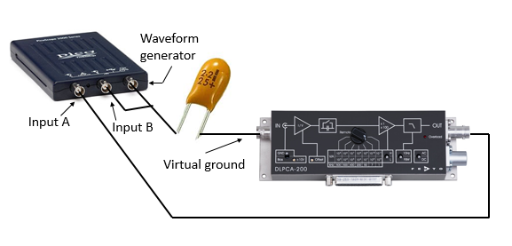
Frequency dependent impedance measurementsTo measure the impedance of a device or circuit, a sinusoidal voltage is applied to the device and the resulting sinusoidal current is measured. The current can have a phase shift with respect to the voltage. As an example, the impedance of a capacitor was measured by connecting the waveform generator of a Picoscope 2208A to one side of a capacitor while the other side of the capacitor was connected to the input of a Femto DLPCA200 transimpedance current amplifier. The input of the current amplifier acts like a virtual ground so the voltage across the capacitor is just the voltage of the waveform generator. The output of the current amplifier is a voltage that is proportional to the current it measures.
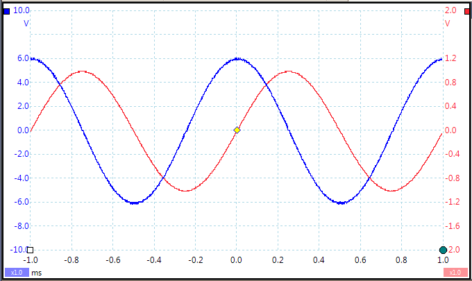
The figure below shows the current through and the voltage across the capacitor. The current (blue) leads the voltage (red) by 90°.
Impedance is often expressed as a complex number $Z$. In the complex representation, sinusoidal motion along the real axis is related to circular motion in the complex plane. The currents and voltages are also complex quantities in this representation, $V=IZ$. The complex representation of harmonic motion
The filled red circle represents the position of the complex number $e^{i\omega t}$ as it moves around the unit circle with angular frequency $\omega$. The open circles represent the position of $\cos\omega t$ along the real axis and $i\sin\omega t$ along the imaginary axis. The simulation on the left is a graphical representation of Euler's formula shown on the right. Oscillations that can be described by $\sin\omega t$ or $\cos\omega t$ are called harmonic oscillations. The relationship between circular motion and harmonic oscillations is described easily using complex numbers. Sometimes when we observe a harmonic oscillation it is convenient to imagine that we are looking at circular motion from the side. We can't measure the component of the motion in the imaginary direction; we just imagine it. Below is another simulation where the solid red point represents a harmonic voltage across a capacitor and the solid blue point represents a current through the capacitor. In the complex representation, there is a fixed angle between the phasor that represents the voltage and the phasor that represents the current. We express the current phasor as $I_0e^{i\omega t}$. The complex impedance of a capacitor is $Z=\frac{1}{i\omega C} = \frac{e^{-\pi/2}}{\omega C}$. The voltage is then $V = IZ = \frac{I_0e^{i(\omega t -\pi/2)}}{\omega C}$. Measuring the impedance a function generator, an oscilloscope, and a transimpedance current amplifier.To measure the impedance of a device you can apply a sinusoidal voltage across the device and detect the current through the device using a transimpedance current amplifier. The applied voltage and output of the current amplifier can be observed with an oscilloscope to determine the amplitude and phase of the signals. This is the configuration illustrated at the top of this page.
Measuring the impedance with a Stanford 830 lock-in amplifierThe Stanford 830 lock-in amplifier has an internal sine-wave generator and a current amplifier that can be used to measure impedance. Connect one side of the device to to the 'SINE OUT' connector and the other side to the input labeled 'A/I'. Use the 'Freq' and 'Ampl' buttons to set the frequency and amplitude of the output voltage by turning the knob. Use the 'Input' button to select the current input 'I(106)'. Select 'Ground' and use 'AC' coupling for frequencies above 160 mHz. The time constant should be long compared to the frequency that is used (~$100/f$). Press the 'Auto Gain' button to select the correct sensivitity. |