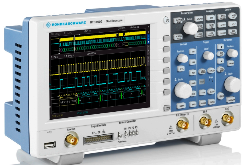
The Rhode & Schwarz RTC1002 is a 2-channel oscilloscope with a built-in waveform generator. It has a maximum sampling rate of 2Gs/sec.
The Web interface 129.27.158.75 will let you save screenshots of the oscilloscope display, send SCPI commands to the instrument, and download the data that is displayed on channel 1 or channel 2.
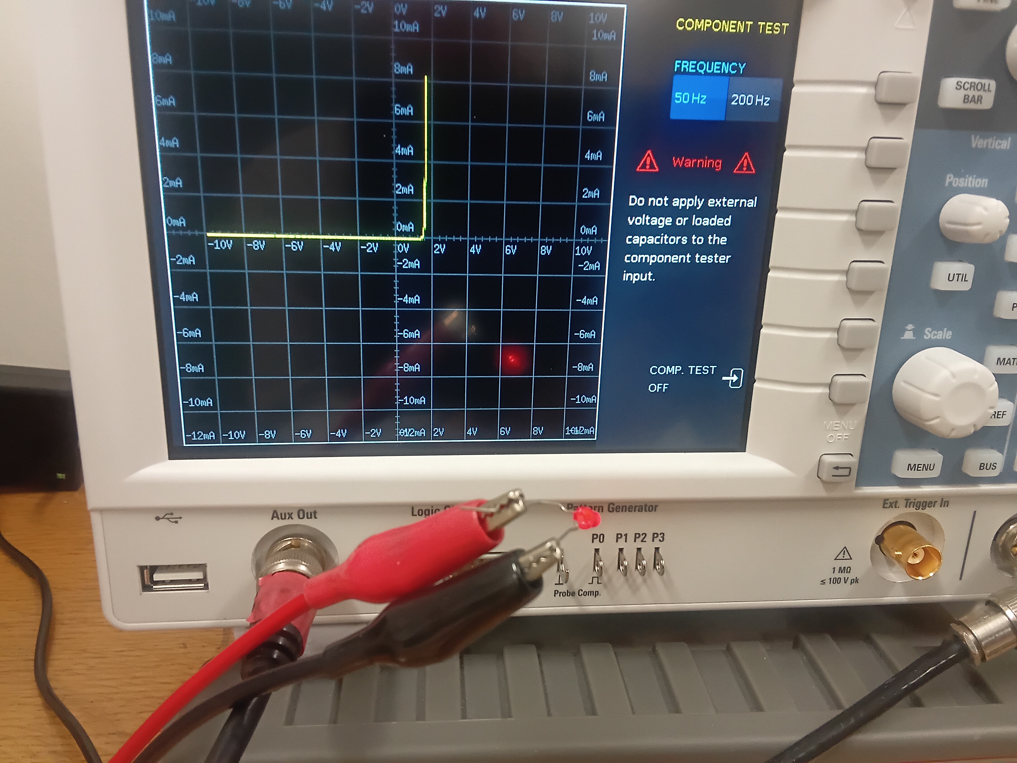
There is a simple component tester that will plot the current-voltage characteristics of a device like a diode or a resistor. Press the button to bring up a list of utilities and then select COMP. TEST with a soft button.
Attach a cable that has a BNC connector on one end and two alligator clips on the other end to the Aux Out port. Clip the device to be tested on the other end of the cable.
The component test function.
If you want to record the data of a current-voltage characteristic, you will need a transimpedance amplifier such as Femto DLPCA-200 to convert the current to a voltage because the oscilloscope can only read a voltage. To use the internal function generator, connect the Aux Out port to Channel 1 and then continue with a BNC cable to apply the voltage from the Aux Out across the device to be tested. Connect the center conductor of the BNC cable to one side of the device to be tested. Connect the other side of the device to be tested to the center conductor of the BNC cable that is connected to the input of the transimpedance amplifier. Connect the two outer conductors of these BNC cables together. Connect the output of the transimpedance amplifier to Channel 2.
Press and select the function generator.
Choose the Function soft button and use the 'Select' knob to choose 'Sinusoid'.
Choose the Frequency soft button and use the 'Select' knob to set a low value such as 11 Hz. Avoid frequencies such as 5 Hz or 10 Hz that have a simple rational relation to 50 Hz.
Choose the Amplitude soft button and use the 'Select' knob the amplitude of the voltage signal.
Choose the Offset soft button and use the 'Select' knob the offset of the voltage signal. For a resistor, an offset of zero is suitable. For a silicon diode, an offset of -1.5 V is suitable and for a light emitting diode an offset of -1.5 V is suitable.
Adjust the horizontal scale to show a few wavelengths and adjust the vertical scale of channel 1 and channel 2 separately. Use dc coupling for both channels. You may have to change the gain on the transimpedance amplifier.
Check that the overload light does not light up on the transimpedance amplifier. If the light is on, adjust the amplitude of the function generator to a smaller value or go to a smaller amplification on the transimpedance amplifier.
Press the button, go to the second page, and choose X-Y mode. Press the CH1 button.
X-Y mode
If you are happy with the current-voltage characteristic, run the following program to record the data.
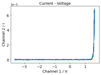
Current-voltage characteristics of a diode.
Capacitance/impedance measurements
The frequency dependent impedance of a device is $Z(\omega ) = V(\omega )/I(\omega )$ where $V(\omega )$ is the amplitude of an sinusoidal voltage signal at angular frequency $\omega$ across the device and $I(\omega )$ is the amplitude of resulting sinusoidal current signal passing through the device. If we assume a harmonic form for the voltage, $V = V_0e^{i\omega t}$, then for a resistor,
This means that the current lags the voltage by 90 degrees.
A circuit involving multiple resistors, capacitors, and inductors can display a resonance, and generally, the phase will be a function of the frequency.
It is instructive to first measure a resistor and a capacitor with known values. We will use the Keithley Model 3390 Arbitrary Waveform Generator to generate an AC voltage. Connect the output of the Keithley 3390 to Channel 1 with a BNC cable, and then continue with another BNC cable, and connect the center conductor of the BNC cable to one side of the device to be tested. Connect the other side of the device to be tested to the center conductor of the BNC cable that is connected to the input of the transimpedance amplifier. Connect the two outer conductors of these BNC cables together. Connect the output of the transimpedance amplifier to Channel 2. On the Keithley 3390, select a sinusoidal waveform. The oscilloscope should display the the sinusoidal voltage on Channel 1 and the sinusoidal current on Channel 2. For a resistor the current and the voltage should be in phase and for a capacitor, the current and voltage should be out of phase.
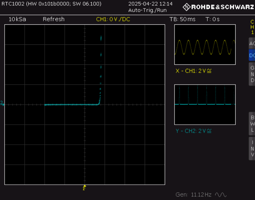
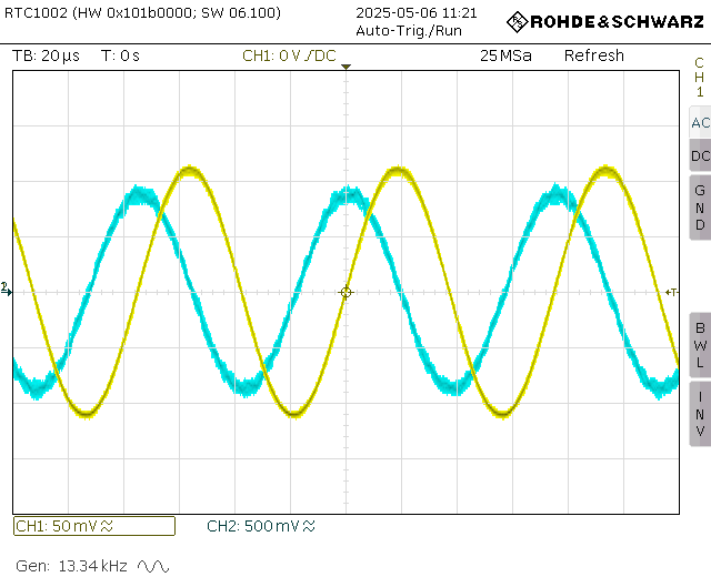
When measuring a capacitor while the scope is triggering on the positive slope of the voltage signal at a level of 0 V, the current should have a maximum at the center of the screen. The oscilloscope screen should look something like this:
CH1 (yellow) is the voltage output by the function generator. CH2 (blue) is the voltage output of the transimpedance amplifier.
Change the frequency of the function generator. For a resistor we expect that the amplitude stays constant and that the current and voltage are in phase for all frequencies. For a capacitor we expect that the amplitude of the current changes, $|I|= \omega CV_0$, and the current leads the voltage by 90°. We could try to read the amplitude and the phase of the current from the oscilloscope screen, but it is better to project both signals onto sine and cosine functions. We express the voltages on Channel 1 and Channel 2 in terms of sine and cosine.
The amplitude of $V_1$ is $A_1 = \sqrt{a_{s1}^2 + a_{c1}^2}$ and the phase is $\phi_1 = \text{atan} (a_{c1}/a_{s1})$. There are similar expressions for $V_2$. The impedance is,
$$Z = \frac{A_1g}{A_2} e^{i(\phi_1-\phi_2)}, $$
where $g$ is the gain of the transimpedance amplifier. For a resistor, $R = Z$ and $\phi_1 - \phi_2 =0$, while for a capacitor, the capacitance is,
$$C = \frac{1}{2\pi f |Z|}$$
and the phase shift should be $\phi_1 - \phi_2 =-90$.
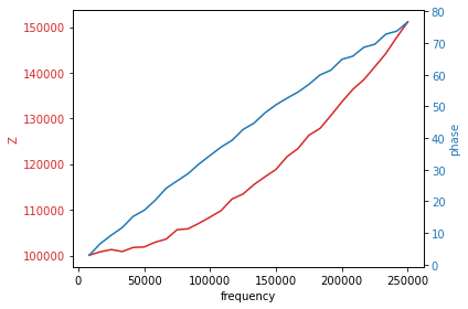
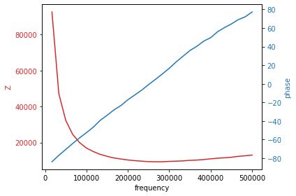
The plots below show the measured impedance for a 100 kΩ resistor on the left, and a 100 pF capacitor on the right. The resistance measurement is correct in the limit of low frequencies but at higher frequencies both the amplitude of the impedance and the phase are not what is expected. The problem is that gain of the transimpedance amplifier decreases with frequency and the amplifier adds a phase shift to the signal. For measuring resistances, we could restrict ourselves to low frequencies but this is not a suitable solution for capacitances. The current through a capacitor is proportional to frequency so it vanishes at low frequency. Notice also that the impedance is going up for the capacitor at high frequencies when we expect it to go down.
100 kΩ resistor
100 pF capacitor
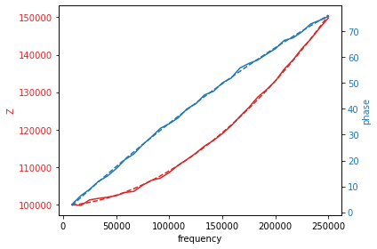
To compensate for the frequency dependence of the transimpedance amplifier, a resistor is measured where we assume that the impedance is frequency independent and any variation from this is ascribed to the amplifier. The impedance and the phase shift of the resistor are fit to parabolic functions. The following code will perform this fit. Adjust the gain and the frequency so that a stable image is displayed on the oscilloscope. It is necessary to input the time base (TB in the upper-left corner of the oscilloscope) and the gain of the transimpedance amplifier into the program. The program selects frequencies that correspond to an integer number of wavelengths in the recorded time series.
The impedance of a 100 kΩ resistor. The dashed line are fits to the data.
Different fit parameters have to be used for each gain setting of the transimpedance amplifier. The same program above is copied below but now it has been modified so that is uses the fit parameters to correct the measurement. Copy the fit parameters in and measure a resistor or a capacitor. If all goes well, the resistance and the capacitance will be freqeuncy independent.
Capacitance - Voltage measurements
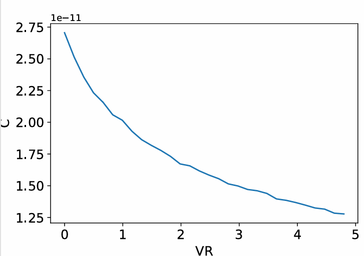
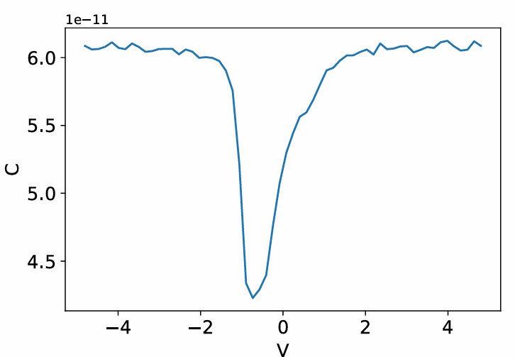
Capacitance - voltage measurements can provide information about the doping concentrations in a diode or a MOSFET. The measurement can be performed either with the internal function generator of the oscilloscope or an external function generator. The code below uses a Keithley Model 3390 Arbitrary Waveform Generator.
Connect the output of the Keithley 3390 to Channel 1 with a BNC cable, and then continue with another BNC cable, and connect the center conductor of the BNC cable to one side of the device to be tested. Connect the other side of the device to be tested to the center conductor of the BNC cable that is connected to the input of the transimpedance amplifier. Connect the two outer conductors of these BNC cables together. Connect the output of the transimpedance amplifier to Channel 2. On the Keithley 3390, select a sinusoidal waveform and a suitable frequency. The amplitude should be 0.1 V or less so that the ac signal does not modulate the depletion region too much. Find the gain setting and range of frequencies that yield a good signal. Change the offset voltage, 'Vos', and you should see the capacitance change for different reverse bias voltages. Each gain setting of the transimpedance amplifier has a bandwidth setting. Don't use frequecies higher than those listed for the gain setting. Set the time scale of the oscilloscope to show about 5 periods of the oscillation. Use a resistor to fit the frequency dependence of the amplifier as described above. The higher the gain setting, the larger the value of the resistor you need to get a good measurement. Once you have made the fit, copy the fit parameters into the program below. As a check, find a capacitor with a capacitance about the same as the diode and measure that first. The following program will change the bias voltage and measure the capacitance at each bias voltage.