Semiconductor Laboratory
|
|
Semiconductor Laboratory | |
|
|
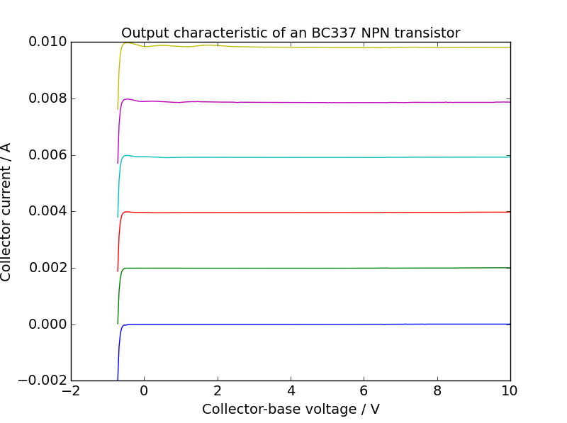
NPN bipolar transistor measurements with a sourcemeterThis page describes how to use a Keithley 2600 Series Sourcemeter to measure the characteristics of an NPN bipolar transistor. We will start with a common base configuration. Common base The base is the middle lead of the transistor. Connect the Hi of channel A to one of outside leads of the transistor, the Hi of channel B to the other outside lead of the transistor and the common ground to the base at the middle lead. Download the Python script npn_common_base.py and the Python library Keithley 2600 Python library and save them in your bipolar-transistor directory . Review the script to see what it does and then run it. Swap the outer leads (emitter and collector) and run the script again. One of these orientations is forward-active mode (which is usually what is wanted) and the other is reverse-active mode. The transistor will work in either direction but it suffers from punchthrough at low voltages in reverse-active mode. In forward-active mode, the emitter is connected to channel B. For negative collector-base voltages, both junctions are forward biased and the collector current is dominated by the forward biased collector-base junction. When both junctions are forward biased, this is called saturation.
Common emitter Review this script to see what it does then run it. The current gain is the ratio of the collector current to base current, $$\beta=\frac{I_C}{I_B}.$$It is also possible to swap the emitter and collector terminals here and you will once again see that punchthrough is an issue.
The slope of the curves is caused by the Early effect. Use the data file to make plots of \(\beta=I_C/I_B\) as a function of \(V_{CE}\). |